If we want the flip flop output to be zero we will activate clear input of that flip flop. When the pre-set is zero then the output of the flip Q is equal to 1. If we want to set 1 in a flip flop we then we will apply zero to that flip flop because it is active low input. The pre-set and clear are active low inputs. The ORI is a signal that is given to the overriding inputs of the flip flops. Now we will store one bit in flip and with the clock its position will be change. The clock is given to all the four flip flops simultaneously at the same time that is why it is synchronous counter and also we have use the overriding inputs. The output Q0 of the first flip flop will be given to the input D1 of the second flip flop, the output Q1 of the second flip flop will be given to the input D2 of the third flip and output Q2 of the third flip flop will be given to the input of the fourth flip flop and the output Q3 of the fourth flip flop will be given to the input of the first flip flop. In case of ring counter the number of states is equal to the number of flip flops used. Suppose we have 4 bit ring counter and we have use four flip flops and to find the number of states we will find it by using the formula:įrom the above we know that we have 16 states and it will count from 0 to 15 but it is when we have normal counter but this is special type of counter in which we cannot find the states like this. The number of states in general when we have four bit counter we use four flip flops. Q 3 which is the output of the last flip flop is connected to the input of the first flip which isD 0 But in case of shift register we do not have any feedback like this but we have only Q 3 as an output and this is the only change we will find in the ring counter. If we compare the ring counter with the shift register there is only one change. In ring counter the output of the last flip flop is connected with the input of first flip flop. We will use D flip flop for its construction. In ring counter we store one bit in flip flop and it will rotate in the whole system. So, for T 1 , T 2, T 3 and T 4 we got 1, Q 1, Q 1.Q 2 and Q 1.Q 2.A ring counter is typical application of the shift register. Step 3: After making the excitation table the next thing to do is dig out the equation from the boolean algebra or K map for the design of the counter.

Similarly, if Q 4 is 0 and Q 4‘ is 1 then T 3 become 1.

When Q 4 =0 which is present state and Q 4‘=0 which is next state then T 4 become 0 State Table with excitation table Present State So, the above table is the excitation table for T Flip Flop. So check the excitation table for T flip flop Which is: T Flip Flop Excitation Table Present state Note: To construct excitation table from state table you should know the excitation table of respective flip flop, in this case, it is T flip flop. Step 2: After that, we need to construct a state table with excitation table. So, in this, we required to make 4 bit counter so the number of flip flops required is 4. we can find out by considering a number of bits mentioned in the question.

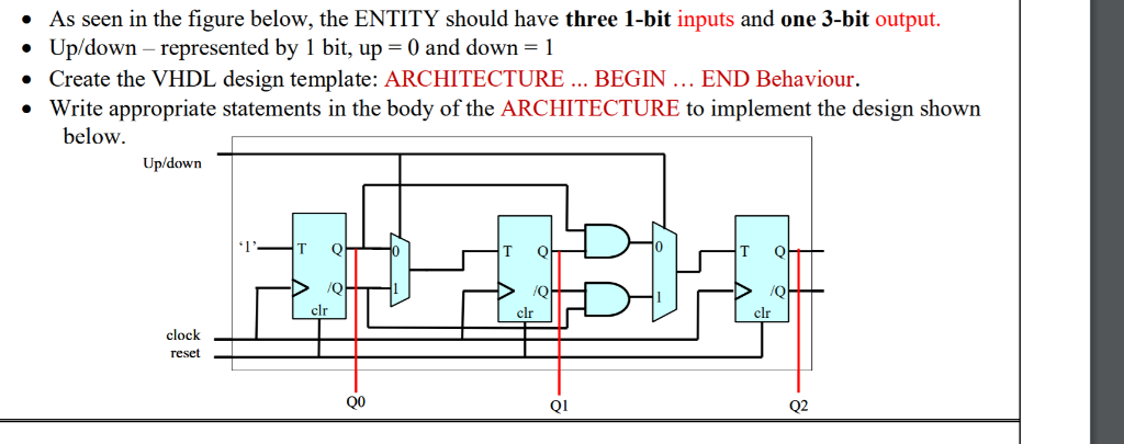
Step 1: To design a synchronous up counter, first we need to know what number of flip flops are required. These are the following steps to design a 4 bit synchronous up counter using T flip flop:


 0 kommentar(er)
